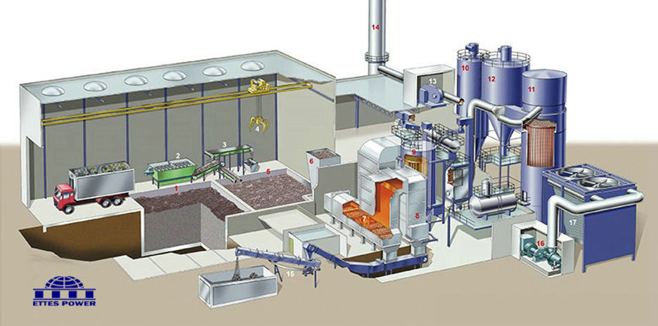
The Components of the Waste to Energy Plant
A typical Waste to Energy Plant would contain the following main components:
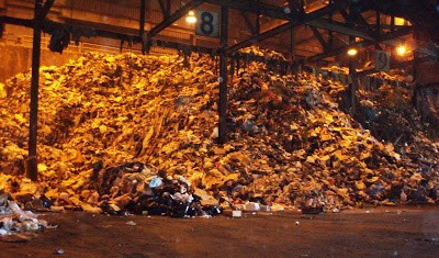
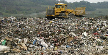
The Tipping Floor & Refuse Bunker:
The tipping floor is the place where the trucks unload the municipal solid waste (MSW) into the refuse bunker. The refuse bunker is divided into separate
regions called cells.
The MSW is stacked vertically in order to conserve cell
space. The new MSW is checked to ensure that large
items such as mattresses, large metal objects, etc.
do not impede combustion in the burner.
Aeration is very important for the reduction of intense
putrid odors in the refuse bunker. The MSW is frequently
moved in order to promote aeration. Induced draft fans
are a necessity to reduce the putrescible odors.
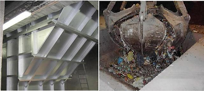
Feed Chute & Hydraulic Ram:
The process of removing the MSW from the refuse bunker
begins with the grapple operator. A grapple
crane operator controls a device, which scoops the
MSW from the refuse bunker and carries it over to the
feed chute. The purpose of the feed chute is to control
the amount and characteristics of the MSW that are
beingfed into the later burner stages. The hydraulic ram
located at the bottom of the feed chute pushes the MSW onto the burner grates.
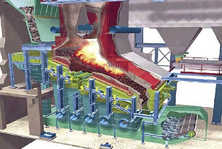
The Combustion Chamber:
Combustion is the process by which a fuel is oxidized by the chain reaction
of radicals, which release heat and convert fuel to products such as ash
and flue gas in a furnace. Combustion is desirable because of a large
reduction in the overall volume of the fuel results. There are three key
elements that are required for combustion: Fuel, Air, and Temperature.
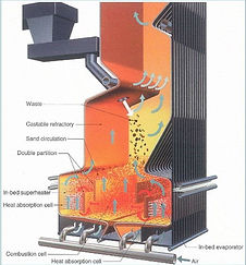
Fuel:
The Fuel for this process is the refuse that enters the burner
via the use of a hydraulic ram pushed onto a stoker grate.
The stoker grate is a series of fixed and moving grate bars
which are sloped downward. The purpose of the stoker
grates is to agitate the MSW to improve combustion. Flue
gas and ash are the products of the combustion process.
The grate is located on a decline to remove the ash that has
settled back onto the grates during combustion. The ash travels as a separate flow path through the plant. The ash volume produced by combustion is three times smaller than the original volume of the MSW. The flue gas then continues to heat the boiler.
Temperature:
The temperature required for combustion is a very important part of the process. The production of pollutants such as NOx, CO is a function of the temperature of the burner. See the section on air pollution control systems for more information regarding the formation and control of these pollutants. The temperature of combustion is dependent on three things, the number of fugitive emissions from the burner, the type of fuel combusted, and the amount of air supplied to the system. Each type of fuel fed varies the amount of heat released from the process. One of the largest concerns of the combustion of MSW is the fact that the fuel feed stream is not homogeneous. The lack of homogeneity requires greater control over the process. A major source of temperature loss from the combustor is the fugitive heat losses due to air pressure leakages, loose flanges etc. Air pressure leakages can also act as a fugitive source of emissions. The amount of air provided to the system can also affect the rate of oxidation of the fuel and therefore the temperature of the burner. The greater the amount of oxygen provided in the fuel the greater the oxidation rate and thus the greater the heat release from the complete oxidation of the fuel.
Air:
The air for the burner is provided by two sources, underfire air, and overfire air. Underfire air is used to control the height of the burner flame. The control of the burner flame height is important to ensure the longevity of the parts located in the combustor. Overfire air is used to prevent the flame from coming into contact with the side walls of the burner.
As noted in the previous section the amount of oxygen provided to the flame can be the limiting concentration that allows for combustion. For most combustion processes, excess air is required.
What is excess air?
Excess air means that the amount of air required for combustion in the actual process exceeds the amount of air, which is predicted theoretically by the stoichiometry of the process.
The percent excess air for the combustion process can be calculated by:
Amount of air actual - Amount of air theoretical
% Excess air = ----------------------------------- (1)
Amount of air theoretical:
It is also important to consider the concentration of the Nitrogen (79 Wt %) in the air. The nitrogen can react with the oxygen to form pollutants such as NO and NO2. This will need to be addressed by the air pollution control equipment later in the process.
Boiler Operation:
One of the advantages of a waste to energy process over a strict
incineration process is the ability to generate electricity. Steam
produced in the boiler is the focal point of electricity generation.
Demineralizer:
The source of the boiler feedwater is the demineralizer unit.
A demineralizer utilizes ion exchange to eliminate hardness ions
(Calcium and Magnesium) and inorganic salts such as NaCl and
NaSO4. The demineralized water must contain little contamination
prior to entering the boiler unit to prevent the formation of silica
and iron oxide vapor in the steam leaving the boiler unit.
The boiler feedwater undergoes heat exchange with the flue gas
stream in the economizer unit.
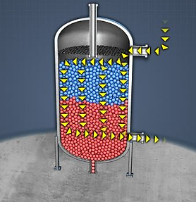
Deaeration:
The presence of dissolved gases such as oxygen, ammonia and carbon monoxide in the boiler feedwater can cause corrosion in the boiler drum. The concentration of the dissolved gases is directly related to their partial pressure. The greater the
pressure exerted on a gas-liquid system at constant
temperature, the greater is the concentration of dissolved gases
in the liquid. The temperature also can impact
the ability of the gases to dissolve into the liquid. If the
temperature is raised, the concentration of dissolved gases
in the liquid will decrease. At the boiling point, the
dissolved gases will be at their minimum concentration.
This statement is also expressed as Henry’s Law.
Pressure Deaeration is a process, which utilizes both the effect of pressure and temperature on the solubility of dissolved gases. The steam is sent through the boiler feedwater stream to raise the boiler feedwater temperature to within a few degrees of the boiling point. The steam contributes a negligible partial pressure, which at temperatures near the boiler feedwater’s boiling point minimizes the solubility of the dissolved gases. There will be approximately 2% percent dissolved oxygen remaining in the boiler feedwater after deaeration is complete. To further remove the remaining dissolved oxygen chemical oxygen scavengers such as Hydrazine, Volatile Organic Compounds or Sodium Sulfite need to be added to the solution.
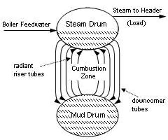
Cycling of Feedwater through the Boiler Drum:
The heated boiler feedwater is carried to the boiler drum by pipes referred to as downcomers. The feedwater is then sent through the boiler drum several times to maximize the amount of steam formed. Pipes referred to as risers carry the liquid/vapor stream back into the boiler drum.
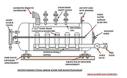
Boiler Drum:
A boiler drum is a unit, which is rated at a certain temperature and pressures to force the boiler feedwater into the vapor phase (steam). As the vapor
phase is formed the liquid level in the drum decreases.
It is important to maintain control of the liquid level in
the boiler drum to prevent damage to the unit.
Complex control schemes have been developed to
control the level of the drum by adjusting the rate of
flow, the inlet temperature, etc. The steam formed in
the boiler drum still contains a certain percent of liquid
content. This liquid contained in the steam is referred
to as the quality. The two-phase system that is formed
(liquid & vapor) in the boiler drum is then cycled through the boiler several times before it is sent to
the superheater unit.
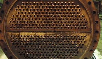
Convection Tubes:
The convection tubes are where the cooler water being fed to the boiler drum and the liquid/steam mixture exiting the boiler drum exchange heat in order to
further raise the temperature of the boiler feedwater. The heat
exchange between the liquid feedwater stream and the liquid
/steam exit stream occurs through the use of a fluid as the
medium of heat transfer. This type of heat transfer is referred
to as convection.
Mud Drum:
The Mud drum is a unit, which is located beneath the boiler drum to collect the solid materials, which precipitate out of the boiler feedwater due to the high
pressure and temperature conditions of the boiler. The process
by which suspended solids are collected in the boiler is
referred to as cycling. Cycling occurs because the boiler
feedwater is sent throughout the boiler drum a number of
times. This is done to produce the maximum amount of steam
per unit volume of feedwater. On each run through the boiler
drum, a portion of the boiler feedwater is vaporized. This
results in an increase in the solids concentration in the boiler
drum. Eventually, the solids concentration hinders the ability
to maintain steam generation efficiency. At this time, a stream
of compressed air is used to blow the solids into the mud drum beneath the boiler. The mud drum, then stores these materials for later disposal. This process of using compressed air to remove the collected suspended solids is referred to as blowdown.
Chelating & Dispersing Agents:
Chelants such as EDTA and NTA are molecules, which have sites to form complexes. They are generally weakly acidic in nature. Chelants are particularly useful
because the complexes that they form are water-soluble. This
allows suspended solids contained in the feedwater to be
solubilized or contained in the solution. This reduces the amount
of cycling in the boiler and increases the period of operation
between blowdown. Chelating agents are used for treating
iron oxide and additional hardness ions that are found in the
boiler feedwater stream. These ions are present due to the water
added to the boiler feedwater stream to maintain the level of the
boiler drum. This water is called the makeup water. The Chelan is
added the feedwater side of the pump discharge line. This is
done in order to form the complex prior to the entrance of the
boiler drum. Control must be maintained over the Chelants feed stream in order to prevent the Chelants from complexing with the magnetite film formed on the boiler drum. This film acts as a protective layer to the boiler unit surface. Unfortunately, the Chelants may not complex all of the suspended solids in the boiler drum. A dispersing agent needs to be added to prevent any additional particles that remain un-complexed from growing larger. Dispersants are anionic polymers, which impede the crystal formation of the suspended solids. Dispersants act on surface-to-surface and particle-to-particle attractions, which are the primary mechanism for the agglomeration of suspended solids in the boiler drum.

Activated PO4 Treatment:
Adding phosphate (PO4-) to the boiler drum is another method of treating suspended solids in the boiler feedwater stream.
The activated PO4 treatment
results in the formation of insoluble
precipitates in the boiler drum.
Unlike the chelation treatment, this
process is carried out solely in the
boiler drum. The goal of the
treatment is to precipitate calcium
and hardness ions in the phosphate
form. The PO4 is particularly
effective for the treatment of iron
deposits on boiler surfaces. These deposits act as miniature boilers taking liquid from the feedwater and producing steam. During this process, iron deposits act to hold caustics and suspended solids within the deposit. This causes depositional growth on the surface of the boiler. PO4 acts to remove the deposits and buffer the pH when the caustic is released. In order to control the size of the precipitate that is formed, Dispersing agents are used to controlling the particle size of the precipitate. Dispersants interfere with the crystal complex of the suspended solid.
An activated PO4 treatment is not as effective as chelation for treating magnesium hardness. Magnesium Phosphate formed by this process adheres to the surface of the boiler and reduces its effectiveness

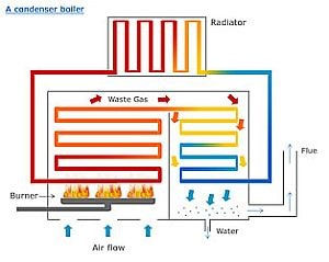
Economizer:
An economizer is a heat exchanger, which acts to preheat the boiler feedwater by transferring heat from the flue gas stream. The flue gas stream contains excess
heat from the combustion process.
Why the heat exchanger is called an economizer?
The heat exchanger is referred to as an economizer because
for every 40 degrees Fahrenheit, which the flue gas
temperature is decreased, there is a one percent increase in
the thermal efficiency of the plant. As the thermal efficiency of
the plant increases, the plant saves money by utilizing the heat
from an existing source instead of requiring heat from another
external source.
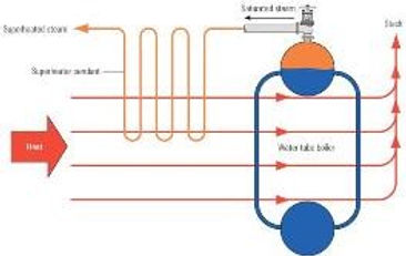
Superheater:
The steam that is produced in the boiler has a certain percentage of moisture content. This moisture content is referred to as the quality of the steam. Due to the
high velocities of the steam inside a turbine, the moisture
content of the steam can shear the turbine blades. A
superheater is utilized to remove the moisture content in
the steam. Raising the temperature above while keeping the
pressure constant does this. Steam, which undergoes this
process, is referred to as superheated steam. The degrees of
superheat are a term, which is used, describes the
temperature difference between the raised temperature and
the temperature at constant pressure. Let’s clarify this further by giving an example.
Example of Degrees of Superheat:
T=350 C, P=8 atm
T=612 C, P=8 atm
Degrees of Superheat=612-350=272 C
Steam Turbine:
A turbine is a device, which generates a network by passing a fluid, such as steam, through a series of rotating blades. The blades are
perpendicular to the flow direction of
the steam. The steam expands in the
turbine due to the pressures below
atmospheric created by a condenser
attached to the turbine. The expansion
of the steam results in the rotation of
the turbine blades. The rotating
blades are attached to a shaft.
This shaft does mechanical work on
the A/C windings of the electrical
generator.
Electric Generator:
The Electrical Generator contains three A/C windings, which are spaced 120 degrees apart. These windings consist of a magnet, which is
encased, in the wire. The magnet
creates a magnetic field. The work
done by the blades on the windings
results in a motion, which is
perpendicular to the magnetic field. A
current is generated due to this motion
in a direction, which predicted by the
right-hand rule. The right-hand rule
states that this direction is
perpendicular to both the motion of
the windings and the magnetic field.
The wires on the A/C windings have a
resistance associated with them. The voltage drop produced by the A/C windings is dependent on the product of the current and the resistance. This statement is defined as Ohm’s Law.
Condenser:
The condenser is a device, which is used to convert the steam back to the liquid phase. A multiple pass shell and tube heat exchanger is used to maximize the
amount of heat transfer with water from the cooling tower.
The water circulated from the cooling tower returns to the cooling
tower to be atmospherically cooled. The liquid formed from the
steam, the condensate is then recycled back to the back into the
boiler feedwater stream. It should be noted that during the
condensation process a number of gases become dissolved in the
condensate. These dissolved gases are treated by the deaerator.
Air Pollution Control Systems:
WTE facilities are one of the largest emitters of sulfur and nitrogen oxides and carbon monoxide. Due to the combustion process, there is an enormous number of
particulates, or fly ash, produced and emitted from the
combustion zone of the incinerator. Hydrochloric acid,
dioxin/furans, cadmium, lead, and mercury are also emitted due
to the random and sometimes unknown composition of the fuel
stream. In order to reduce these emissions and comply with
federal regulations, air pollution control devices are a necessity.
Particulater:
The outlet gas stream of a WTE is full of fly ash, carbonaceous material that is a result of poor combustion practices. Ideally, particulates should be minimized to
almost none, but the fuel stream of a WTE is such that particulates will
be produced. Fortunately, it is against the law to emit tons of fly ash
directly into the atmosphere. For this reason, particulate removal
systems were designed, built and put into operation. The most common
particulate removal systems are bag filters and electrostatic precipitators
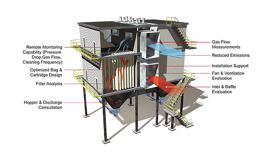
The Baghouse:
A Baghouse is basically a large box with forty to one hundred 6” diameter and 12-foot long bags located inside it for the effective removal of
particulates from .01 micrometers to
100 micrometers in diameter. They are
situated vertically, and the dirty flue gas
enters through one side of the house near
the bottom and exits the other side near the
top, with 99% of the particulates removed.
The bag filters nominally use a woven fabric
for collection. The collection process is not
merely a screening or a filtration of the dust
since the openings in the cloth are many
times the size of the dust particles collected.
The efficiency of a new bag may be low for a few moments until it develops a precoat of dust that serves as the filtering layer. Once precoated, the bag usually retains sufficient solids in its pores so that it does not return to its original efficiency.
The filtration process becomes inefficient after the bags have been saturated. It is at this moment that a control system will engage a cleaning mechanism. Popular cleaning mechanisms are through shaking or high-pressured air. The former method simply shakes the particulates of the bags, which fall into a hopper at the bottom of the baghouse. The latter method utilizes high-pressured air injected at the top of the baghouse to spray the particulates off the bags and into the hopper. The only downfall to the shaking method is higher ware on the bags and possible tearing.
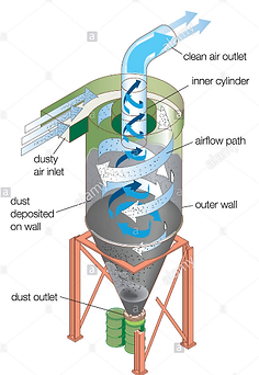
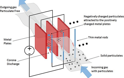
Electrostatic Precipitator:
The Electrostatic Precipitator, or ESP as it is affectionately called, is also a large box. However, it contains long metal plates, upon which particulates are
collected. The collection is based on imparting a
charge to particles in an electric field, which then
causes them to migrate and deposit on a collection
plate of the opposite charge. Liquids agglomerate on
the collection plate and drain off, but solids must be
removed by rapping, which is similar to shaking.
When power is applied to a preceptor, no current flows
until a sufficient voltage is achieved to create a corona
discharge (gas ionization) at the discharge electrodes.
Then particle charging, and deposition begins. As the
voltage is increased further, the field strength becomes more intense and precipitator efficiency increases until the point where spark-over or arcing from the discharge electrode to the collecting plate occurs.
For maximum collection efficiency, the voltage should be maintained just short of spark over. Unfortunately, spark over potential is an operating variable affectedly changes in temperature; dust resistively, moisture content, and frequency and efficiency of removal of collected dust. For maximum operability, the difference in potential between the start of corona and spark over should be as large as possible. This difference decreases as gas temperature increases or system absolute pressure decreases. The difference is greater for negative-polarity current than for positive. Because of this, most WTE ESP’s are run with negative polarity.
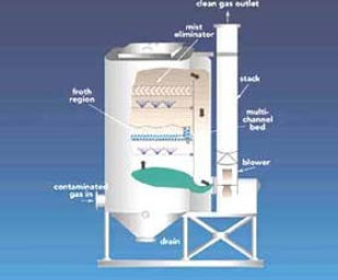
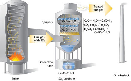
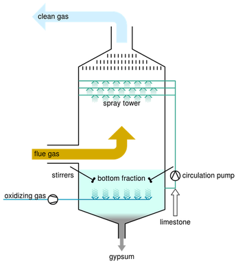
Lime Scrubbing:
Nitrogen Oxides, Sulfur Oxides, as well as various other pollutants can be successfully “scrubbed” out of the flue gas stream using a process
called Lime Scrubbing. Lime, CaCO3, is a
neutralizing agent, which reacts with the acid
gasses in the gas stream. The products of the
reaction are calcium salts and can be used in
cement manufacturing. The lime scrubbing process
takes place in a reaction chamber, usually 25 feet in
length and 5 feet in diameter. The reaction chamber
provides reaction time for complete conversion of
the acid gasses with the lime. There are several
methods of Lime Scrubbing and they can be
incorporated before or after the particulate removal device.
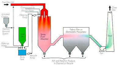
Spray Dryer or Semi-Dry System:
Lime is delivered in a slurry form that is mixed with water, to a reaction chamber where it is atomized into fine droplets. These droplets evaporate into the
reaction chamber and the reagent reacts with the
acid gas in the wet form at the boundary of the
droplet and continues to react in the dry state after it
exits the reaction chamber. The acids are converted to
dry salts that are filtered, along with the ash and toxic
materials.
Dry Injection or Dry-Dry System:
Lime is injected in a dry state before the baghouse and
reacts with the acids as it is airborne and as part of the
filter cake on the bags. All the solids are removed, as
described in the Baghouse/ESP sections.

Dry-Wet System:
In some cases, a wet scrubber is used after the baghouse to either improve the acid gas scrubbing, perform all of the acid scrubbings, and/or improve the
condensation and removal of gaseous toxic materials.
This wet scrubber can be added to either of the above dry
scrubber arrangements or can be used without any previous
acid gas scrubbing. 9.5 Induced Draft Fan.
An essential part of the air pollution control system is the
Induced Draft Fan. It is located between the air pollution
control units and the stack. It is necessary for proper flow
through the system. The flow must be fast enough to keep
particulates from settling out in the ductwork, as well as
strong enough to overcome the pressure drops across all
control equipment. Fans can beeither centrifugal or axial
type. The shape of the vanes on the fan characterizes them.
The fan vane shapes improve efficiency and ease of
maintenance depending on the type of gas stream it is
handling.
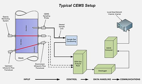
Continuous Emissions Monitoring System aka CEMS:
More importantly than anything else in an air pollution control system is its monitoring system. It can be said that an APC system is only as good as its CEMS. For we must know exactly what is coming out of our stack in order to keep good control. CEM systems are located before the stack and measure a number or parameters:
PM - Particulate Matter less than 10 micrometers
SO2
HCl
NOx
CO
Dioxin/Furan
Cadmium, Lead, Mercury
Opacity - visibility of the plume gas
The CEM system consists of several pieces. First, a sample of gas is extracted from the ductwork or stack using a probe. The probe samples continuously, hence the name. The sample is then sent, through piping, to analyzers located within the plant. Prior to analysis, the gas is put through a filter to remove all moisture. Then, using spectral and refractive methods, the concentration of a pollutant is determined. The major drawback to this is the enormous amounts of data that is now being generated. For this, several computers are attached to the analyzers and compile the data. There are many software companies selling programs to compile the data and then give the user the ability to manipulate the data to generate reports, tables, charts, and most anything the user has in mind. The programs are usually very flexible and anyone with a logical thought process can generate their own personalized reports
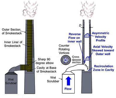
Emission Stack:
The final element of an air pollution control system is the stack. The main reason it is part of the control system is that of the dispersion factor.
The natural atmosphere has the ability to cleanse itself
throughdispersion of particulates and gases
throughout its vast volume. Unfortunately, man has
added more pollutants than the atmosphere can
handle. Due to this fact, stacks must be made high
enough to disperse the limited pollutants into the
atmosphere. The GEP, or general engineering practice,
for obtaining stack height is governed by this equation:
Hs = 2.5 * Hb
Essentially, build the stack 2.5 times as high as the
tallest building in the plant.
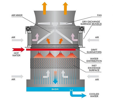
Cooling Tower:
The cooling tower is a structure used to cool the water, which is sent to the condenser to perform heat exchange with the steam exiting from the turbine.
Two of the more common methods for cooling are
direct air contact and fan cooling. Indirect air contact,
the cooling water is stored and the temperature
gradient between the cooling fluid from the
condenser and the ambient air is sufficient to produce
heat transfer to the atmosphere. Cooling towers
designed for small pipes containing the heated fluid
from the condenser characterize fan cooling. Large
radial fans blow air across these pipes. This produces
sufficient temperature gradients for heat transfer with
the air.