
The Waste to Energy Plant

The Waste to Energy Plant
Waste-to-Energy plants are typically in operation over 80% of the time generating a continuous supply of electricity and steam. In order for a plant to continuously operate at optimum capacity, it is required that the facility have an appreciable amount of on-site storage space for MSW. Storage pits are generally sized such that they can supply the boilers enough fuel to run for a minimum of three days at normal capacity. The reason for this 3-day minimum is a result of waste collection service typically been in operation only 5 days per week with the need to handle holidays that can keep the waste collection inactive for three full days. The operating capacity of WTE plants ranges from 500- 3000 tons per day, requiring that the storage pit be large enough to store nearly 10,000 tons of MSW for high throughput operations.
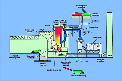
A typical waste to energy site can be separated into four major components:
-
The Receiving Area
-
The Grate
-
The Boiler and Power Generator
-
The Air Pollution Control (APC) System
Due to strict environmental regulations, the APC system can occupy more than half of a facilities footprint.
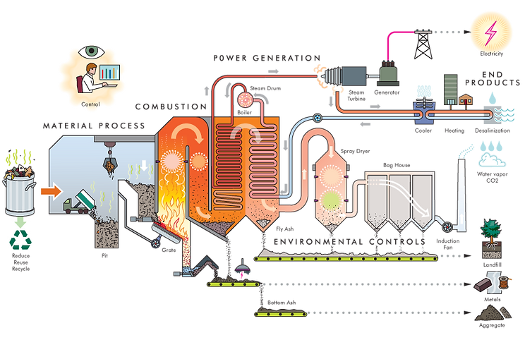
The Process
Raw Material:
Using waste as a combustion material can reduce landfill volumes by more than 90 percent. Waste to Energy prevents one ton of CO2 release for every ton of waste burned and eliminates methane, that would have
leaked with landfill disposal. Best practices rely on the "three Rs": Reuse, Reduce, Recycle.
Recycling plastics, glass, paper, metals, and wood from the waste stream reduces the carbon and
pollutants created in the burn process. Materials such as kitchen refuse, bio-waste, and commercial
garbage are ideal for combustion.

Material Process:
Waste material is received in an enclosed receiving area, where it is more thoroughly mixed in preparation for combustion. Negative airflow will carry dust and odor into the
combustion chamber from the receiving area, along with the waste to eliminate
its spread outside the facility.

Efficient Combustion:
Mixed waste enters the combustion chamber on a timed moving grate, which turns it over repeatedly to keep it exposed and burning—the way turning over or poking a
fireplace log brightens the fire. A measured injection of oxygen and fumes are
drawn from the receiving area makes for a complete burn.

Fly Ash Capture:
Although fly ash is captured throughout the process, the finest airborne particulates are removed in the filter baghouse, where an induction fan draws air through the fabric bags
toward the stack or chimney. This process removes 96 percent of any remaining
particulates. The bags are vibrated at intervals to shake loose particulates caked
on their inner and outer surfaces. Captured fly ash is often returned to landfills.

Acid Gas Treatment:
The acidic combustion gasses are neutralized with an injection of lime or sodium hydroxide. The chemical reaction produces gypsum. This process removes 94 percent of the
hydrochloric acid.
Bottom Ash Recycling:
The unburned remains of combustion—"bottom ash"—are passed by magnets and eddy current separators to remove both ferrous (steel and iron) and other metals—such as
copper, brass, nickel, and aluminum—for recycling. The remaining ash can be
used as aggregate for roadbeds and rail embankments. Ash is generated at a
ratio of about 10 percent of the waste’s original volume and 30 percent of the
waste’s original weight.

Steam Power Generation:
Highly efficient superheated steam powers the steam turbine generator. The cooling steam is cycled back into water through the condenser or diverted as a heat source for
buildings or desalinization plants. Cooled stream is reheated in the economizer
and superheater to complete the steam cycle.

Mercury and Heavy Metal Capture:
Activated carbon (charcoal treated with oxygen to increase its porosity) is injected into the hot gases to absorb and remove heavy metals, such as mercury and cadmium.

NOX Treatment Dioxins/Furans Treatment:
Nitrogen oxide in the rising burn gases is neutralized by the injection of ammonia or urea. Dioxins and furans are destroyed by exposing flue gases to a sustained temperature of
1,562°F/850°C for two seconds. This process removes more than 99 percent of
dioxins and furans.

Electric Power and Heat:
A 1,000 ton-per-day WTE plant produces enough electricity for 15,000 households. Each ton of waste can power a household for a month. If combined with a cogeneration
plant design, WTE plants can, while producing electricity, also supply heat
for nearby businesses, desalination plants, and other purposes.

Monitor and Control:
The air stream rising to the stack is continuously monitored to ensure compliance with air quality standards. The entire process can be controlled to optimize efficiency in the
combustion, heat and steam generation, electrical energy, and environmental
processes.control
The Efficiency of a Typical
Waste to Energy Power Plant
Latent Heat and the WTE Plant:
Latent heat is the quantity of heat absorbed or released by a substance undergoing a change of state, such as ice changing to water or water to steam, at constant temperature and pressure. Also called heat of transformation. In order to calculate the amount of heat generated/absorbed through a phase change, chemists use the following Specific Heat Formula to drive the heat energy of a substance.
Specific Heat Formula:
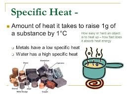
When heat energy is added to a substance, the temperature will change by a certain amount. The relationship between heat energy and the temperature is different for every material, and the specific heat is a value that describes how they relate.
Heat energy = (mass of substance)(specific heat)(change in temperature)
Q = mc∆T
Q = Heat energy (Joules, J)
m = Mass of a substance (kg)
c = specific heat (units J/kg∙K)
∆ is a symbol meaning "the change in"
∆T = Change in temperature (Kelvins, K)
How to calculate the efficiency of a Waste to Energy Plant:
The following table will give an estimated amount of energy in the MSW stream in order to produce energy in an efficient waste to energy plant. Please remember that
the “Calorie” is a unit of heat required to raise the temperature of
1 gm of water by 10C. LHV in the table stands for Low Heating Value,
while HHV stands for High Heating Value, the difference being in the
energy contained in the water vapor created by the combustion.
This energy is typically not recovered.
The following is a typical composition of different components in a waste sample:
